Color Interference
Fantastic colors

High-speed matrix sensor integrated circuit
Enjoy the live photo shot during the camera filter
assembly, when putting a glass based stripe filter onto an
operating(!) CCD sensor. The action was necessary because the
manufacturer did not offer a color version.
And it has worked reproducibly. Thanks to Fraunhofer Institute
(FhG) IOF in Jena we could recognize 150 nanometer shifts of the
filter during movement.
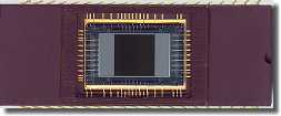
On the right a photo of the black-and-white CCD EG&G Reticon HS0512JAQ area sensor, resolution 512 pixel x 512 pixel at 1 000 frames/sec. The active area, the dark square in the middle, measures 8.19 mm (almost 1/3 inch) edge length.

Drop of glue on optical sensor chip - refraction effects

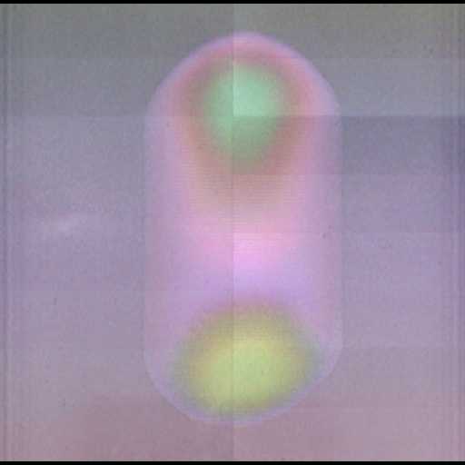
Fault colors due to wrong position interpretation of the not yet
aligned filter
Object
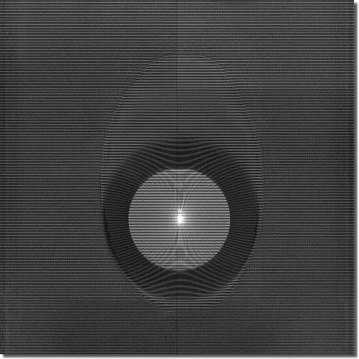
Each photos was made with an opened black-and-white CCD area sensor, which means one with removed glass cover and thus bare silicon chip. View direction: from the active sensor through a drop of glue on the sensor surface onto (and through) a red-green-blue (RGB) stripe filter on glass substrate into the light source. The algorithm for color recovery is partly inactivated yet.
The the photo on the left depicts the glue drop between sensor
surface and the stripe filter. The color algorithm is switched off.
Camera
Easy spoken the black-and-white area sensor works as its
own camera. The exposure is 1/1 000 sec. The photos are a
little bit post processed (contrast and etch enhancing) because too
much light would have cured (i.e. hardened the glue) before
adjusting the filter.
The alignment is done under optical control using the sensor
itself, with an accuracy of ±1/4 micrometer required by
the fill factor close to 100%.
What you see
Explanation: the upper left image was made in the clean
room during filtering the black-and-white sensor. The bright lines
are the green ones of a red - green - blue - green line pattern on
the glass substrate. Each line is 16 microns wide, with an overlap
of approx. 1 micron to each neighbor line.
Viewing at the stack from the side you would see the sensor at the
bottom. Then the glue in an eggcup shape, approx. 0.5 mm
(0.02 inch) high. And on the top the glass substrate
(thickness: 2.0 mm = 0.08 inch) with the filter
pattern.
What you see in the image (just a suggestion): the egg-shaped
contour shows the original size of the glue drop (on the sensor)
before it has gotten in contact with the glass substrate. The dark
ring is caused by the flank of the glue eggcup, because the viewing
direction is against the light source. Its circumference is the
contact area between glue and glass substrate. The inner circle is
the optical path through the glue given by the smallest diameter of
the eggcup. The bright spot in the middle is caused by the lens
effect (focal point) of the glue drop.
It is necessary for the color recovery that the corresponding
algorithm is familiar which color belongs to each pixel, thus the
color filter is fixed and clearly aligned to the pixel. If this is
not given misinterpretation and thus fail colors will occur. In the
image on the lower left the stripe filter is not close enough
lowered to the sensor surface. Of course, the not yet
completely spread glue drop has some influence, too.
The the photo on the left depicts the moment when the stripe
filter reaches the position on top of the glue drop, but has not
been lowered. The color recovery algorithm is activated.
Is what you get

Hand optimized color sensor
End work: after finishing the glue fills the whole gap between sensor die and glass substrate. The distance between them is then approx. 20 to 30 microns. The glue is hardened by UV exposure and the cavity of the sensor (open bond wires!) is sealed by ceramic/epoxy filling and cured in an oven.
The photo on the right shows the finished color coated wide ceramic DIP CCD sensor, molded, cured and ready for the integration into the socket of the camera head.
This so modified chip was exclusively used between 1998 and 2001 in the color version of the high-speed camera Weinberger Speedcam Pro family. For non-scientific cameras the about three hours effort would have been just too expensive.

